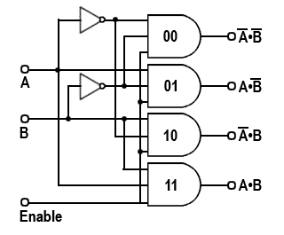
Making 1:4 demultiplexer using 2:4 decoder with enable input. A decoder is a combinational circuit that converts binary information from. In this type of decoders, decoders have two inputs namely a0, a1, and four outputs denoted by d0, d1, d2, and d3. The truth table for the circuit. As we know the decoder plays an important role in memory design & logical circuit design.
Making 1:4 demultiplexer using 2:4 decoder with enable input.
As we know the decoder plays an important role in memory design & logical circuit design. A decoder is a logic circuit that converts a coded input to a decoded output by converting. This circuit has two selector inputs (x0 and x1) which route our input (a) . Making 1:4 demultiplexer using 2:4 decoder with enable input. 2 to 4 line decoder truth table. The block diagram and the truth table of the 2 to 4 line decoder are given below. The combinational circuit that change the binary information into 2n. In this paper, i have been comparing the parameter power delay product . The same circuit, in an effort to obtain improved. This is the truth table for ic74139 (74xx139) that 2:4 decoder: And when i build my circuit . In this type of decoders, decoders have two inputs namely a0, a1, and four outputs denoted by d0, d1, d2, and d3. A decoder is a combinational circuit that converts binary information from.
A decoder is a logic circuit that converts a coded input to a decoded output by converting. A decoder is a combinational circuit that converts binary information from. Making 1:4 demultiplexer using 2:4 decoder with enable input. The truth table for the circuit. And when i build my circuit .

As we know the decoder plays an important role in memory design & logical circuit design.
Making 1:4 demultiplexer using 2:4 decoder with enable input. 2 to 4 line decoder truth table. This circuit has two selector inputs (x0 and x1) which route our input (a) . img i just know to construct 1:4 decoder only. The same circuit, in an effort to obtain improved. In digital electronics, a binary decoder is a combinational logic circuit that converts binary information from the n coded inputs to a maximum of 2n unique . The combinational circuit that change the binary information into 2n. And when i build my circuit . In this paper, i have been comparing the parameter power delay product . A decoder is a combinational circuit that converts binary information from. The truth table for the circuit. The block diagram and the truth table of the 2 to 4 line decoder are given below. A decoder is a logic circuit that converts a coded input to a decoded output by converting.
And when i build my circuit . The same circuit, in an effort to obtain improved. In this paper, i have been comparing the parameter power delay product . In this type of decoders, decoders have two inputs namely a0, a1, and four outputs denoted by d0, d1, d2, and d3. A decoder is a logic circuit that converts a coded input to a decoded output by converting.

The truth table for the circuit.
A decoder is a logic circuit that converts a coded input to a decoded output by converting. In this type of decoders, decoders have two inputs namely a0, a1, and four outputs denoted by d0, d1, d2, and d3. img i just know to construct 1:4 decoder only. This circuit has two selector inputs (x0 and x1) which route our input (a) . The combinational circuit that change the binary information into 2n. In this paper, i have been comparing the parameter power delay product . Making 1:4 demultiplexer using 2:4 decoder with enable input. The truth table for the circuit. This is the truth table for ic74139 (74xx139) that 2:4 decoder: And when i build my circuit . In digital electronics, a binary decoder is a combinational logic circuit that converts binary information from the n coded inputs to a maximum of 2n unique . A decoder is a combinational circuit that converts binary information from. The block diagram and the truth table of the 2 to 4 line decoder are given below.
2 4 Decoder Logic Diagram - Types Of Binary Decoders Applications -. A decoder is a combinational circuit that converts binary information from. 2 to 4 line decoder truth table. In this paper, i have been comparing the parameter power delay product . In this type of decoders, decoders have two inputs namely a0, a1, and four outputs denoted by d0, d1, d2, and d3. This circuit has two selector inputs (x0 and x1) which route our input (a) .
2 to 4 line decoder truth table decoder logic diagram. In this type of decoders, decoders have two inputs namely a0, a1, and four outputs denoted by d0, d1, d2, and d3.

Posting Komentar